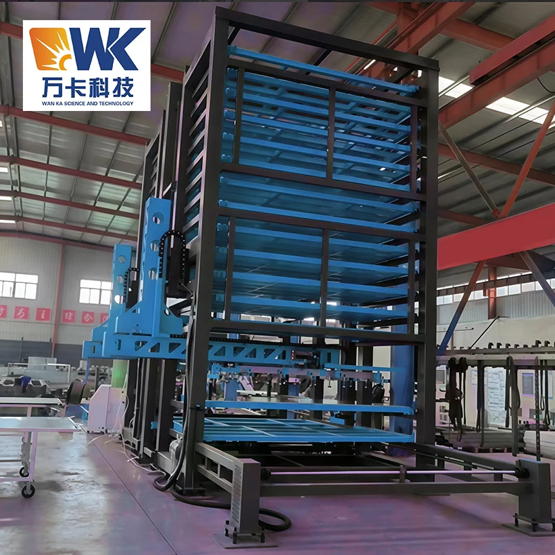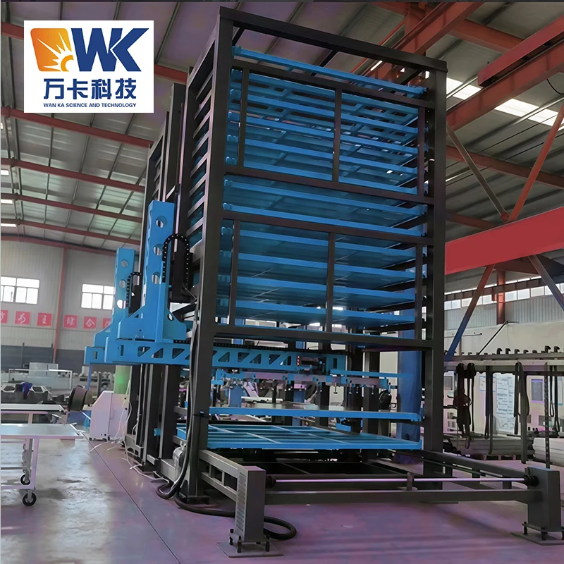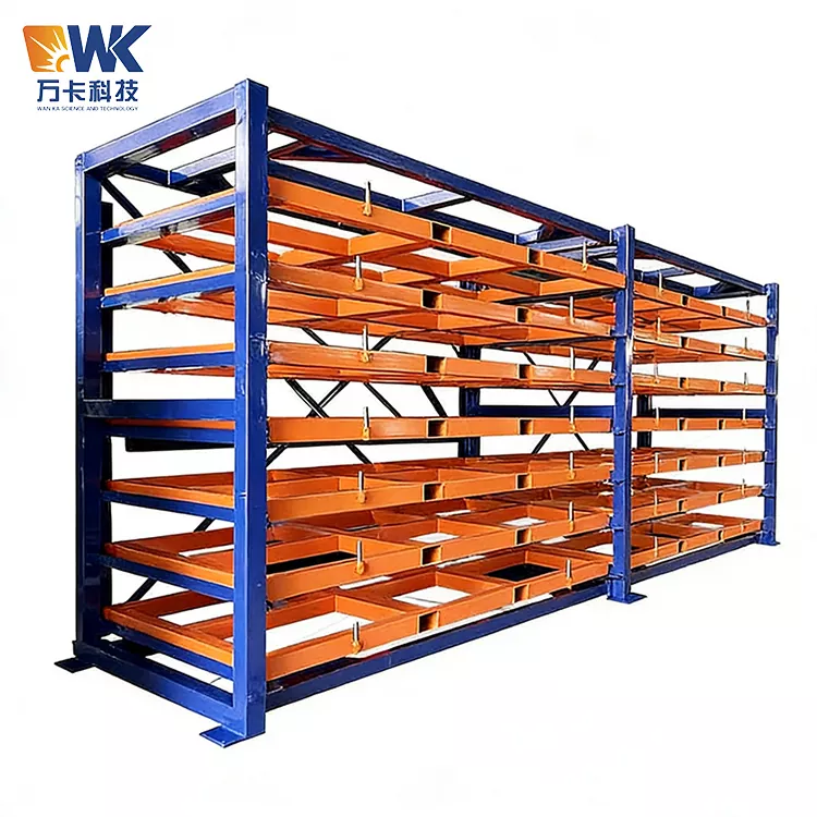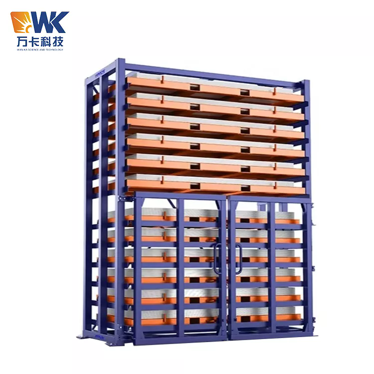
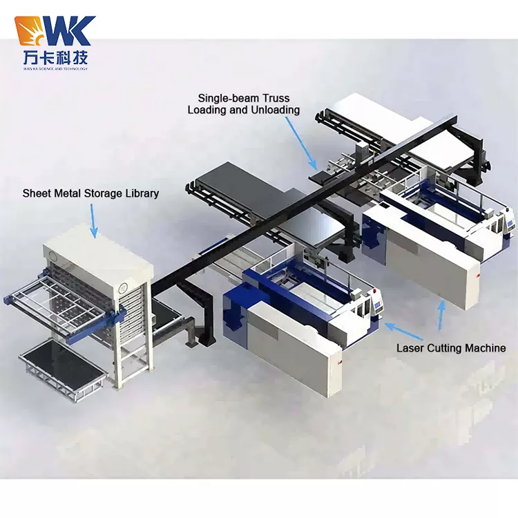
1325 Automatic Laser Loader
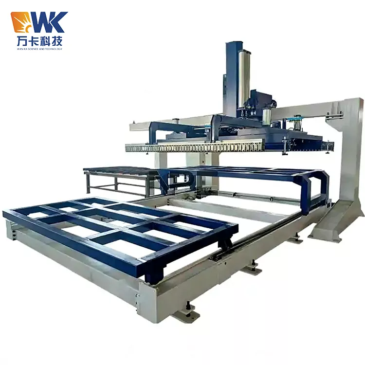
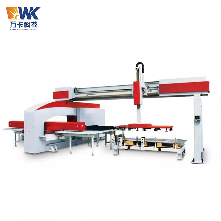
1325 Automatic Laser Loader is an all-in-one automatic loading and unloading equipment developed by Jinan Wanka Technology Co., Ltd. for laser cutting of metal plates with a size of 1300×2500mm. This is one of the most mainstream plate specifications in the sheet metal processing industry - widely used in laser cutting of products such as household appliances, electrical cabinets, computer cases, and automotive parts.
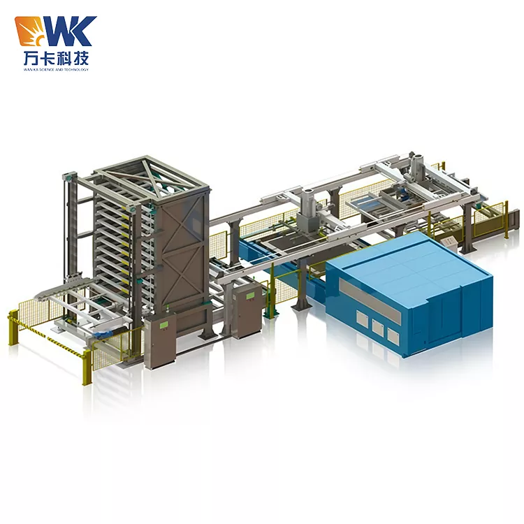
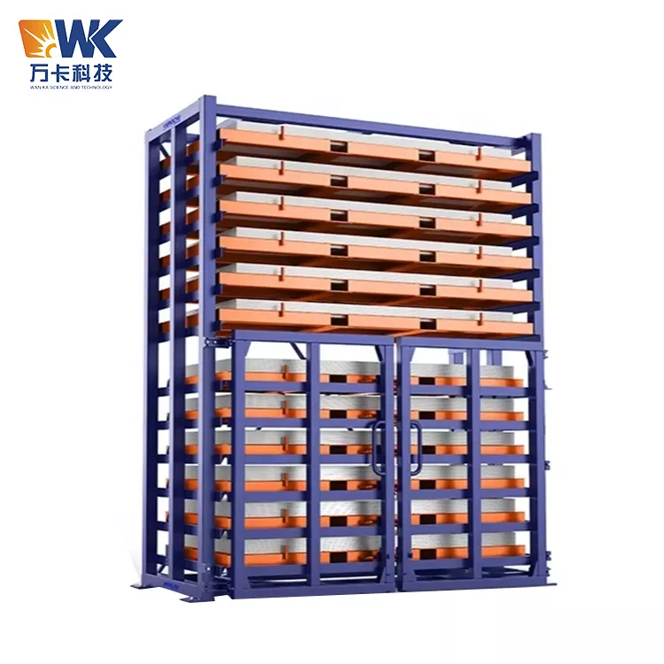
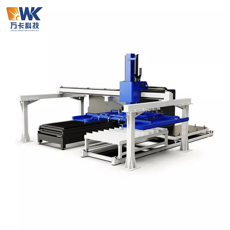
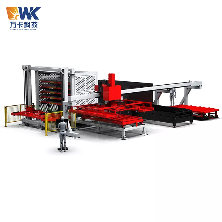
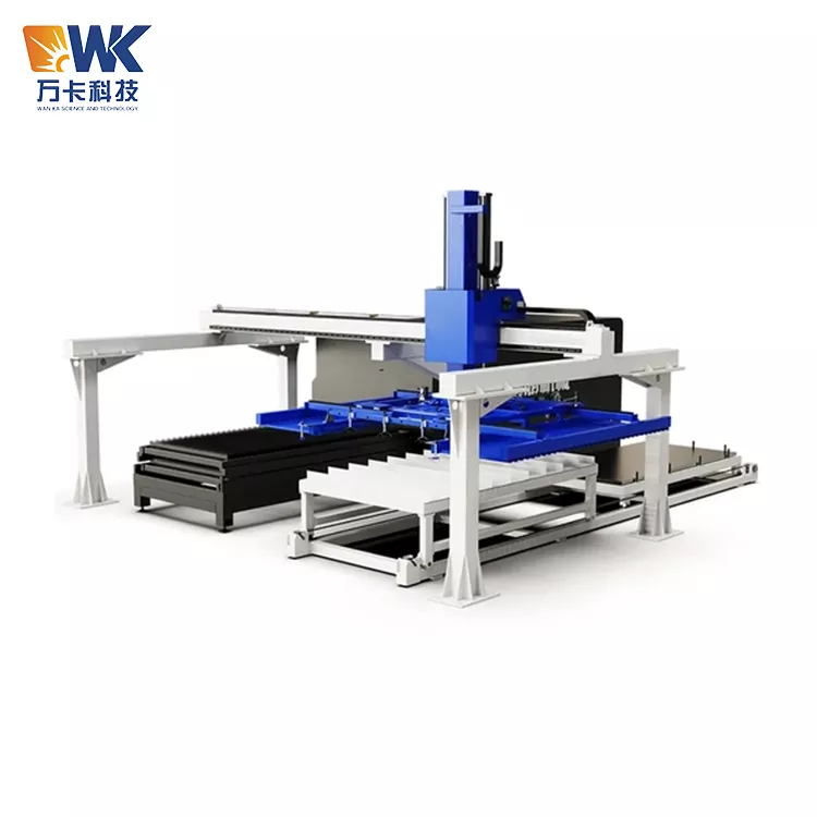
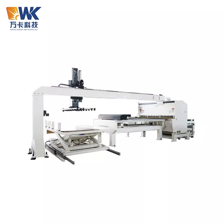
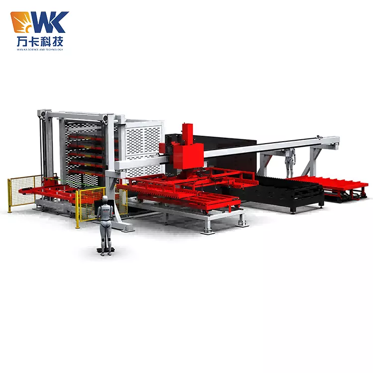
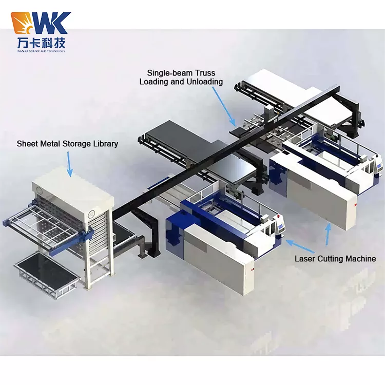
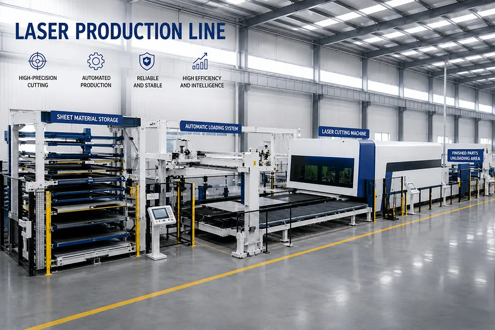
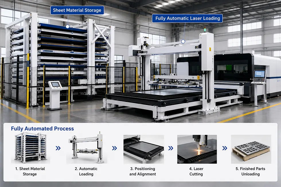
When Wanka Factory was manufacturing this 1325 Automatic Laser Loader, the core design concept was "fully automatic, unmanned, and uninterrupted". It consists of seven modules: the gantry frame mechanical arm, the vacuum suction fixture for loading materials, the clamping fixture for unloading materials in an embracing manner, the X/Y/Z three-axis servo drive system, the automatic raw material lifting platform, the automatic finished product discharging platform, and the PLC intelligent control system. After the system is connected with the laser cutting machine, it realizes a fully automated closed-loop operation from loading raw materials on the board to cutting and discharging the finished products.
The system can meet the 7×24-hour all-day continuous operation requirements without the need for manual intervention. By leveraging the rapid material discharging and loading functions, the utilization rate of the laser cutting machine is maximized.
Core selling points
Loading suction cup + unloading clamping, a combined design covering the entire process
7×24-hour unmanned operation, maximizing the utilization rate of the cutting machine
Vacuum pressure retention + power failure prevention, safety redundant design
Gantry truss structure, high rigidity and high precision
Intelligent control system, one-click model change
Anti-scraping mechanism, protecting the surface of the sheet material
Modular design, highly expandable
Technical Specifications
|
Parameter |
Standard Value |
Customizable Range |
|
Equipment Model |
WK-AL1325 |
Customized per sheet dimensions |
|
Max Sheet Length |
≤2500mm |
Up to 3000mm |
|
Max Sheet Width |
≤1300mm |
Up to 1500mm |
|
Sheet Thickness |
1–25mm (carbon steel) |
Thin-sheet version: 0.5–12mm optional |
|
Payload (Loading) |
300–500kg |
100kg–800kg |
|
Payload (Unloading) |
≤200kg per part |
Subject to workpiece size |
|
Gantry Span |
2500–3500mm |
Subject to workshop layout |
|
Longitudinal Travel (Y-axis) |
4000–6000mm |
Subject to material table & cutter layout |
|
Lifting Travel (Z-axis) |
600–1200mm |
Subject to material table height |
|
X-axis Speed |
0–60m/min (servo adjustable) |
Set on demand |
|
Y-axis Speed |
0–60m/min (servo adjustable) |
Set on demand |
|
Z-axis Speed |
0–20m/min (servo adjustable) |
Set on demand |
|
Repeat Positioning Accuracy |
±0.1mm |
±0.05mm (high-precision option) |
|
Loading Suction Cup Config. |
8–12 sets of vacuum cups |
Arranged per sheet size |
|
Unloading Fork Gripper Config. |
2–4 sets of plug-in grippers + timing-belt scratch-proof mechanism |
Customized per workpiece shape |
|
Vacuum System |
Vacuum generator / electric vacuum pump |
Imported brand optional |
|
Control System |
PLC (Inovance / Mitsubishi / Siemens) + touchscreen |
Per customer specification |
|
Communication Protocol |
Dry contact, RS485, Modbus TCP, Profinet |
Adapted per laser cutter model |
|
Power Supply |
380V/50Hz/3-phase, total power 5–10kW |
Subject to configuration |
|
Air Source Requirement |
0.6–0.7MPa, air consumption 1.5–2.5m³/min |
Subject to cup count |
|
Workshop Clearance Height |
≥4.5m |
Low-profile design down to 4m available |
|
Foundation Requirement |
Concrete floor, thickness ≥200mm, strength ≥C25 |
Calculated per payload |
|
Safety Config. |
Safety light curtain, E-stop, limit switches, vacuum pressure holding |
Optional on demand |
|
Surface Treatment |
Epoxy powder coating (RAL color chart) |
Selected per environment |
Non-standard additional features: A one-to-two scheme can be designed (one mechanical hand serving two cutting machines), visual positioning system, remote monitoring module, automatic thickness detection and double-layer plate detection function.
FAQ
Question 1: What specifications of laser cutting machines can the 1325 Automatic Laser Loader be compatible with?
Answer: The system is compatible with laser cutting machines with a 1300×2500mm paper size. If you have other paper size requirements (such as 1500×3000mm, etc.), we can provide non-standard customization. The system is connected to different brands of laser cutting machines through various communication protocols such as dry contacts, RS485, Modbus TCP, Profinet, etc. It has been adapted to mainstream brands such as Daqin, Benetron, Hongshan, Baishuo, and Trumpf.
Question 2: How are the loading suction cup and the discharging clamping mechanism switched? Is manual intervention required?
Answer: It is a fully automatic switch that requires no human intervention. The system completes the process automatically under PLC control: the suction system is activated when loading, and the gripper-type fixture is switched to when unloading. The entire switching process is controlled by the program, and the operator only needs to set the parameters on the touch screen.
Question 3: Will the push-down material feeding method cause any scratches on the surface of the sheet material?
Answer: No. The system adopts a plug-in type gripper structure. It is inserted and clamped from the edge of the workpiece or the reserved process hole position, avoiding direct contact with the cutting surface. For special occasions where there are requirements for scratches on the surface, an anti-scuffing mechanism can also be equipped. The gripper adopts a synchronous belt anti-scuffing design, effectively reducing the scuffing of the sheet material during cutting.
Question 4: Can the system handle irregularly-shaped cutting parts? For example, parts with holes or irregular shapes?
Answer: Yes. This is precisely the core advantage of the clamping-in design. The suction cup cannot attach to parts with holes or irregular shapes, while the clamping-in claws can grip from the edge of the part or at the process holes, adapting to various shapes of finished products. During system programming, it is necessary to precisely define the clamping-in point and insertion depth.
Question 5: How much installation space is required for the equipment in the workshop?
Answer: The system adopts a gantry truss structure. After installation, the mechanical hand's operating range needs to cover the raw material platform, the laser cutting machine, and the finished product platform. It is recommended that the net height of the workshop be no less than 4.5 meters, and the installation area should be no less than 6 meters in length and no less than 4 meters in width. The specific dimensions will be determined based on the customer's on-site layout design. If the net height of the workshop is insufficient, we can design a height reduction solution.
Question 6: Can the system be connected to any brand of laser cutting machine? Is it necessary to modify the cutting machine?
Answer: Yes. The system offers standard I/O dry contact signals or Ethernet communication interfaces. Simply connect the signal lines such as "processing completed" and "request for material supply" from the cutting machine control cabinet to achieve linkage. Usually, no hardware modification of the cutting machine is required.
Hot Tags: automatic laser loader, laser loader machine, 1325 laser loader
Send Inquiry
Contact Info
-
Address
No. 13 Workshop, Xinglonghai Industrial Park, Jiyang District, Jinan City, Shandong Province, China
-
Tel
-
E-mail
For Sheet Metal Storage, Profile Warehouse, aser Loader or pricing inquiries, share your email—we'll respond within 24 hours.